Details
| Surface Treatment |
Anodized |
Material |
AL 6005-T5 |
| Place of Origin |
China |
Installation Site |
Open Field |
| Brand Name |
Exten |
Model Number |
A02-1 |
| Standard |
|
Certificate |
AS/NZS1170.2/CE/ISO |
| Wind Load |
60m/s(196.85ft/s) |
Module Orientation |
Landscape Portrait |
| Wind speed |
Yo 60m/s |
Max Snow Load |
1.4KN/m2 |
| Snow Load |
1.4KN/m2(29.24psf) |
Service Life |
25YRS |
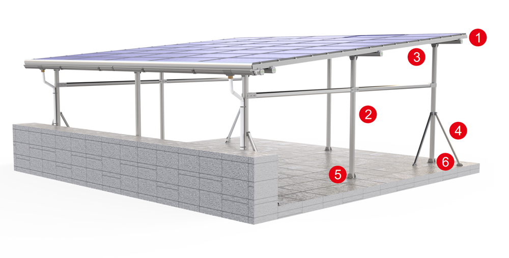
Component List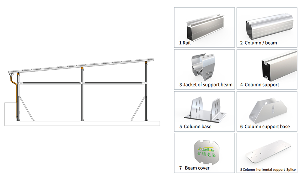
| Description |
Material |
Specificatioin |
Quantity |
| Column 01 |
AL 6005-T5 |
6000mm |
3 |
| Column 02 |
AL 6005-T5 |
2530mm |
3 |
| Rail |
AL 6005-T5 |
3970mm |
12 |
| Column Support 01 |
AL 6005-T5 |
1500mm |
8 |
| Column 1 |
AL 6005-T5 |
3112mm |
3 |
| Column 2 |
AL 6005-T5 |
2806mm |
3 |
| Column 3 |
AL 6005-T5 |
2500mm |
3 |
| Column Portrait Support Splice |
AL 6005-T5 |
3392mm |
4 |
| Rail Cover |
PE |
|
12 |
| Beam Cover |
PE |
|
6 |
| Column Base |
AL 6005-T5 |
160mm |
9 |
| Jacket of Support Beam |
AL 6005-T5 |
150mm |
9 |
| Rail Splice |
AL 6005-T5 |
300mm |
6 |
| Beam Splice |
AL 6005-T5 |
300mm |
3 |
| Beam & Rail Connector |
AL 6005-T5 |
70mm |
36 |
| Column Support Base |
AL 6005-T5 |
80mm |
8 |
| Column Base |
AL 6005-T5 |
150mm |
8 |
| Column Horizontal Support Splice |
AL 6005-T5 |
296mm |
12 |
| Mid Clamp |
AL 6005-T5 |
60mm |
64 |
| End Clamp |
AL 6005-T5 |
60mm |
32 |
Aluminum Alloy Solar Carports Overview
What is aluminum alloy solar carports? The combination of a lightweight, weather-resistant aluminum alloy framework with photovoltaic modules not only enables dual land use but also offers significant advantages in terms of structural load reduction, corrosion resistance, service life, and assembly efficiency. The content covers a breakdown of core advantages, five practical FAQs, and standardized installation steps from foundation to grid connection, providing a basis for decision-making for commercial, industrial, and park projects.
Aluminum Alloy Solar Carports Advantages
Lightweight Design Reduces Load, Directly Lowering Foundation Costs. Aluminum alloy has a density of only one-third that of steel, yet maintains a specific strength close to that of high-strength steel. This means that bending moments at column bases and foundation loads are significantly reduced, making it particularly suitable for sites with limited roof load capacity or average geological conditions. Reduced concrete usage for foundations and shallower pile depths directly lower civil engineering budgets—these savings can sometimes offset the material premium of the mounting system itself.
Weather-resistant and maintenance-free, providing peace of mind throughout the entire lifecycle. After surface treatment via anodizing or fluorocarbon coating, aluminum alloy spontaneously forms a dense oxide film in the atmosphere, making it naturally resistant to salt spray, acid rain, and industrial pollution. Unlike galvanized steel, there is no need for periodic repainting or concern about rust caused by scratches. Even after 25 years of operation in coastal or high-humidity areas, the structural strength of the carport degrades only minimally.
Installation is as quick as building with blocks. The aluminum alloy profiles feature standardized notches and connectors, with all components pre-drilled at the factory, eliminating the need for on-site welding or hot-dip galvanizing. Assembly is achieved simply by bolting the parts together; a three-person team can complete the main frame assembly for a 200-square-meter carport within two days. This significantly reduces the risks associated with working at heights and shortens the construction timeline.
Combining aesthetics with functionality. The silver or dark matte finishes blend seamlessly with modern building facades. Additionally, when supporting double-sided, double-glazed modules, the optimized reflectivity of the aluminum alloy frames provides an extra contribution to rear-side gain—the carport is no longer just a parking space, but a revenue-generating facade asset.
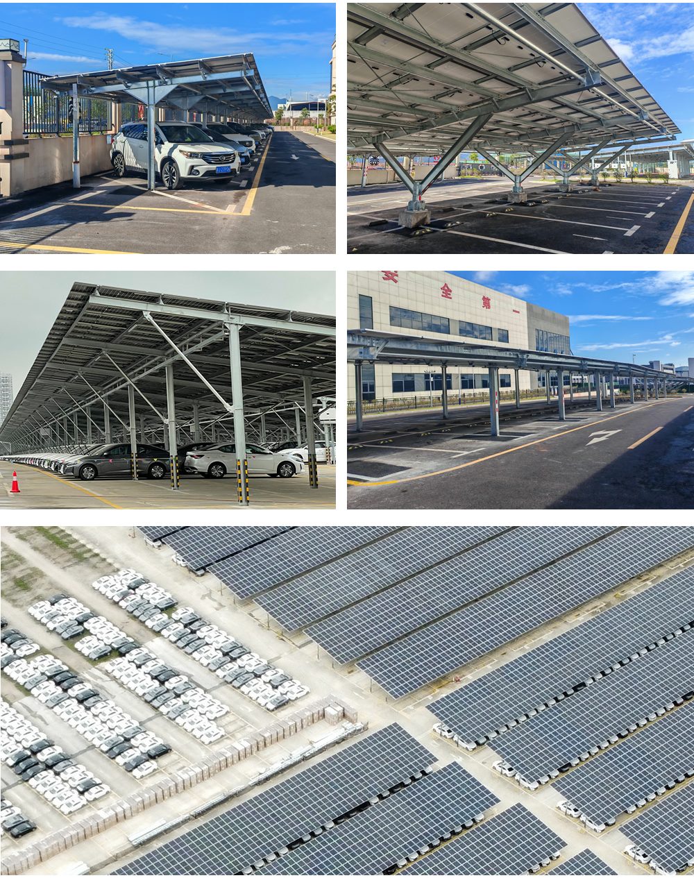
Case
Installation Process
Step 1: Site Survey and Foundation Layout
Verify site elevation, underground utilities, and soil bearing capacity. Use a total station to stake out the column grid coordinates, keeping deviations within ±5 mm. Simultaneously, optimize module layout to minimize cable routes to the inverters and grid-connection cabinets.
Step 2: Foundation Construction and Embedded Component Alignment
Pour independent foundations or drive static-pressure steel pipe piles according to the drawings. Use positioning templates to secure embedded anchor bolts in place; proceed to the next step only after the concrete has reached 75% of its design strength.
Step 3: Column and Main Beam Assembly
After positioning the columns, loosely tighten the nuts. Hoist the main beams into place and secure them using connecting angle brackets and wind-resistant diagonal braces. At this stage, use a level to adjust the column top elevation span by span, with an error of ≤3 mm, then fully tighten all joints.
Step 4: Purlin Installation and Module Laying
Lay the longitudinal purlins in sequence, ensuring that the anti-loosening washers on all bolts face outward. Next, hoist the photovoltaic modules into place and secure each one to the purlins with four clamping bolts, leaving a 12 mm thermal expansion gap between modules.
Step 5: Electrical Wiring and Grounding Connections
Lay the string cables along the reserved cable trays; crimp the MC4 connectors securely and bundle them to prevent disconnection. Simultaneously complete the grounding jumpers for each span; after busbar connection, connect them to the grounding busbar, and verify that the insulation resistance and grounding resistance meet specifications.
Step 6: System Commissioning and Grid Connection Acceptance
Check the torque of all bolts, cable polarity, and the status of circuit breakers. After power-up, test the inverter’s MPPT tracking and anti-islanding protection. Conduct a 2-hour no-load test run to confirm no abnormalities. Finally, clean up the site and hand over the completion documentation.
FAQ
Q1: Can aluminum alloy carports withstand typhoons?
Selected based on local wind pressure and utilizing H-shaped or truss main beams, the design can withstand wind speeds of 45 m/s or higher. The key lies in the connection joints, which can be secured using stainless steel bolts and shear-resistant washers.
Q2: How are PV cables concealed?
Cable access holes are pre-drilled in the main beams and purlins. DC cables are routed along the inner walls of the cavities, with protective sleeves added at the exits to completely prevent exposure and aging.
Q3: Is grounding complicated?
The profiles feature built-in conductive pathways. Connect each span with copper braided tape, and install a grounding electrode at each end to easily achieve a grounding resistance of less than 4 Ω.
Q4: Will the weight of double-glass modules exceed the load limit?
Aluminum alloy mounting frames typically have a load-bearing margin of over 30%, and the purlin spacing can be adjusted to accommodate the support points required for double-glass modules, eliminating the need for additional reinforcement.
Q5: Can the system be expanded or relocated later?
All bolted connections are removable. To expand the system, simply extend the main beams and add additional posts; to relocate it, disassemble and reassemble the structure. The material recovery rate exceeds 95%.


